
Geometrical optics, or ray optics, describes light propagation in terms of "rays". The "ray" in geometric optics is an abstraction, or "instrument", which can be used to approximately model how light will propagate. Light rays are defined to propagate in a rectilinear path as far as they travel in a homogeneous medium. Rays bend (and may split in two) at the interface between two dissimilar media, may curve in a medium where the refractive index changes, and may be absorbed and reflected. Geometrical optics provides rules, which may depend on the color (wavelength) of the ray, for propagating these rays through an optical system. This is a significant simplification of optics that fails to account for optical effects such as diffraction and interference. It is an excellent approximation, however, when the wavelength is very small compared with the size of structures with which the light interacts. Geometric optics can be used to describe the geometrical aspects of imaging, including optical aberrations.
Contents |
[edit]Explanation

A light ray is a line or curve that is perpendicular to the light's wavefronts (and is therefore collinear with the wave vector).
A slightly more rigorous definition of a light ray follows from Fermat's principle, which states that the path taken between two points by a ray of light is the path that can be traversed in the least time.[1]
Geometrical optics is often simplified by making the paraxial approximation, or "small angle approximation." The mathematical behavior then becomes linear, allowing optical components and systems to be described by simple matrices. This leads to the techniques of Gaussian optics and paraxial ray tracing, which are used to find basic properties of optical systems, such as approximate image and object positions and magnifications.[2]
[edit]Reflection
Main article: Reflection (physics)

Glossy surfaces such as mirrors reflect light in a simple, predictable way. This allows for production of reflected images that can be associated with an actual (real) or extrapolated (virtual) location in space.
With such surfaces, the direction of the reflected ray is determined by the angle the incident ray makes with the surface normal, a line perpendicular to the surface at the point where the ray hits. The incident and reflected rays lie in a single plane, and the angle between the reflected ray and the surface normal is the same as that between the incident ray and the normal.[3] This is known as the Law of Reflection.
For flat mirrors, the law of reflection implies that images of objects are upright and the same distance behind the mirror as the objects are in front of the mirror. The image size is the same as the object size. (The magnification of a flat mirror is equal to one.) The law also implies that mirror images are parity inverted, which is perceived as a left-right inversion.
Mirrors with curved surfaces can be modeled by ray tracing and using the law of reflection at each point on the surface. For mirrors with parabolic surfaces, parallel rays incident on the mirror produce reflected rays that converge at a common focus. Other curved surfaces may also focus light, but with aberrations due to the diverging shape causing the focus to be smeared out in space. In particular, spherical mirrors exhibit spherical aberration. Curved mirrors can form images with magnification greater than or less than one, and the image can be upright or inverted. An upright image formed by reflection in a mirror is always virtual, while an inverted image is real and can be projected onto a screen.[3]
[edit]Refraction
| This article should include a summary of or be summarized in another article. See Wikipedia:Summary style for information on how to incorporate it into this article's main text, or the main text of another article. |
Main article: Refraction

Refraction occurs when light travels through an area of space that has a changing index of refraction. The simplest case of refraction occurs when there is an interface between a uniform medium with index of refraction n1 and another medium with index of refraction n2. In such situations, Snell's Law describes the resulting deflection of the light ray:

where θ1 and θ2 are the angles between the normal (to the interface) and the incident and refracted waves, respectively. This phenomenon is also associated with a changing speed of light as seen from the definition of index of refraction provided above which implies:

Various consequences of Snell's Law include the fact that for light rays traveling from a material with a high index of refraction to a material with a low index of refraction, it is possible for the interaction with the interface to result in zero transmission. This phenomenon is called total internal reflection and allows forfiber optics technology. As light signals travel down a fiber optic cable, it undergoes total internal reflection allowing for essentially no light lost over the length of the cable. It is also possible to produce polarized light rays using a combination of reflection and refraction: When a refracted ray and the reflected ray form a right angle, the reflected ray has the property of "plane polarization". The angle of incidence required for such a scenario is known as Brewster's angle.[3]
Snell's Law can be used to predict the deflection of light rays as they pass through "linear media" as long as the indexes of refraction and the geometry of the media are known. For example, the propagation of light through a prism results in the light ray being deflected depending on the shape and orientation of the prism. Additionally, since different frequencies of light have slightly different indexes of refraction in most materials, refraction can be used to produce dispersion spectra that appear as rainbows. The discovery of this phenomenon when passing light through a prism is famously attributed to Isaac Newton.[3]
Some media have an index of refraction which varies gradually with position and, thus, light rays curve through the medium rather than travel in straight lines. This effect is what is responsible for mirages seen on hot days where the changing index of refraction of the air causes the light rays to bend creating the appearance of specular reflections in the distance (as if on the surface of a pool of water). Material that has a varying index of refraction is called a gradient-index (GRIN) material and has many useful properties used in modern optical scanning technologies including photocopiers and scanners. The phenomenon is studied in the field of gradient-index optics.[4]

A device which produces converging or diverging light rays due to refraction is known as a lens. Thin lenses produce focal points on either side that can be modeled using the lensmaker's equation.[5] In general, two types of lenses exist: convex lenses, which cause parallel light rays to converge, and concave lenses, which cause parallel light rays to diverge. The detailed prediction of how images are produced by these lenses can be made using ray-tracing similar to curved mirrors. Similarly to curved mirrors, thin lenses follow a simple equation that determines the location of the images given a particular focal length (f) and object distance (S1):

where S2 is the distance associated with the image and is considered by convention to be negative if on the same side of the lens as the object and positive if on the opposite side of the lens.[5] The focal length f is considered negative for concave lenses.
Incoming parallel rays are focused by a convex lens into an inverted real image one focal length from the lens, on the far side of the lens. Rays from an object at finite distance are focused further from the lens than the focal distance; the closer the object is to the lens, the further the image is from the lens. With concave lenses, incoming parallel rays diverge after going through the lens, in such a way that they seem to have originated at an upright virtual image one focal length from the lens, on the same side of the lens that the parallel rays are approaching on. Rays from an object at finite distance are associated with a virtual image that is closer to the lens than the focal length, and on the same side of the lens as the object. The closer the object is to the lens, the closer the virtual image is to the lens.
Likewise, the magnification of a lens is given by

where the negative sign is given, by convention, to indicate an upright object for positive values and an inverted object for negative values. Similar to mirrors, upright images produced by single lenses are virtual while inverted images are real.[3]
Lenses suffer from aberrations that distort images and focal points. These are due to both to geometrical imperfections and due to the changing index of refraction for different wavelengths of light (chromatic aberration).[3]
[edit]Underlying mathematics
| This article needs attention from an expert on the subject. See the talk page for details. WikiProject Mathematics or the Mathematics Portal may be able to help recruit an expert. (June 2009) |
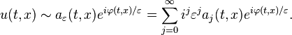
As a mathematical study, geometrical optics emerges as a short-wavelength limit for solutions to hyperbolic partial differential equations. In this short-wavelength limit, it is possible to approximate the solution locally by

where k,ω satisfy a dispersion relation, and the amplitude a(t,x) varies slowly. More precisely, the leading order solution takes the form
- a0(t,x)eiφ(t,x) / ε.
The phase φ(t,x) / ε can be linearized to recover large wavenumber  , and frequency
  . The amplitude a0 satisfies a transport equation. The small parameter
  enters the scene due to highly oscillatory initial conditions. Thus, when initial conditions oscillate much faster than the coefficients of the differential equation, solutions will be highly oscillatory, and transported along rays. Assuming coefficients in the differential equation are smooth, the rays will be too. In other words, refraction does not take place. The motivation for this technique comes from studying the typical scenario of light propagation where short wavelength light travels along rays that minimize (more or less) its travel time. Its full application requires tools from microlocal analysis.
, and frequency . The amplitude a0 satisfies a transport equation. The small parameter enters the scene due to highly oscillatory initial conditions. Thus, when initial conditions oscillate much faster than the coefficients of the differential equation, solutions will be highly oscillatory, and transported along rays. Assuming coefficients in the differential equation are smooth, the rays will be too. In other words, refraction does not take place. The motivation for this technique comes from studying the typical scenario of light propagation where short wavelength light travels along rays that minimize (more or less) its travel time. Its full application requires tools from microlocal analysis.[edit]A simple example
Starting with the wave equation for 

assume an asymptotic series solution of the form
Check that

with
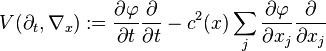
Plugging the series into this equation, and equating powers of ε, the most singular term O(ε − 2) satisfies the eikonal equation (in this case called a dispersion relation),

To order ε − 1, the leading order amplitude must satisfy a transport equation
- 2Va0 + (Lφ)a0 = 0
With the definition , ω: = − φt, the eikonal equation is precisely the dispersion relation that results by plugging the plane wave solution  into the wave equation. The value of this more complicated expansion is that plane waves cannot be solutions when the wavespeed c is non-constant. However, it can be shown that the amplitude a0 and phase φ are smooth, so that on a local scale there are plane waves.
, ω: = − φt, the eikonal equation is precisely the dispersion relation that results by plugging the plane wave solution into the wave equation. The value of this more complicated expansion is that plane waves cannot be solutions when the wavespeed c is non-constant. However, it can be shown that the amplitude a0 and phase φ are smooth, so that on a local scale there are plane waves.To justify this technique, the remaining terms must be shown to be small in some sense. This can be done using energy estimates, and an assumption of rapidly oscillating initial conditions. It also must be shown that the series converges in some sense.
[edit]References
- ^ Arthur Schuster, An Introduction to the Theory of Optics, London: Edward Arnold, 1904 online.
- ^ Greivenkamp, John E. (2004). Field Guide to Geometrical Optics. SPIE Field Guides vol. FG01. SPIE. pp. 19–20. ISBN 0-8194-5294-7.
- ^ a b c d e f g Hugh D. Young (1992). University Physics 8e. Addison-Wesley. ISBN 0201529815.Chapter 35
- ^ E. W. Marchand, Gradient Index Optics, New York, NY, Academic Press, 1978.
- ^ a b Hecht, Eugene (1987). Optics (2nd ed. ed.). Addison Wesley. ISBN 0-201-11609-X. Chapters 5 & 6.
[edit]External links
INTERFERENCE (Optics)
In physics, interference is a phenomenon in which two waves superimpose to form a resultant wave of greater or lower amplitude. Interference usually refers to the interaction of waves that are correlated or coherent with each other, either because they come from the same source or because they have the same or nearly the same frequency. Interference effects can be observed with all types of waves, for example, light, radio, acoustic, and surface water waves.
Contents |
[edit]Mechanism

The principle of superposition of waves states that when two or more waves are incident on the same point, the total displacement at that point is equal to the vector sum of the displacements of the individual waves. If a crest of a wave meets a crest of another wave of the same frequency at the same point, then the magnitude of the displacement is the sum of the individual magnitudes – this is constructive interference. If a crest of one wave meets a trough of another wave then the magnitude of the displacements is equal to the difference in the individual magnitudes – this is known as destructive interference.
| combined waveform |  | |
| wave 1 | ||
| wave 2 | ||
| Constructive interference | Destructive interference | |
Constructive interference occurs when the phase difference between the waves is a multiple of 2π, whereas destructive interference occurs when the difference is π, 3π, 5π, etc. If the difference between the phases is intermediate between these two extremes, then the magnitude of the displacement of the summed waves lies between the minimum and maximum values.
Consider, for example, what happens when two identical stones are dropped into a still pool of water at different locations. Each stone generates a circular wave propagating outwards from the point where the stones were dropped. When the two waves overlap, the net displacement at a particular point is the sum of the displacements of the individual waves. At some points, these will be in phase, and will produce a maximum displacement. In other places, the waves will be in anti-phase, and there will be no net displacement at these points. Thus, parts of the surface will be stationary—these are seen in the figure above and to the right as stationary blue-green lines radiating from the centre.
[edit]Between two plane waves


A simple form of interference pattern is obtained if two plane waves of the same frequency intersect at an angle.
One wave is travelling horizontally, and the other is travelling downwards at an angle θ to the first wave. Assuming that the two waves are in phase at the point B, then the relative phase changes along the x-axis. The phase difference at the point A is given by
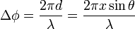
It can be seen that the two waves are in phase when
 ,
,
and are half a cycle out of phase when

Constructive interference occurs when the waves are in phase, and destructive interference when they are half a cycle out of phase. This, an interference fringe pattern is produced, where the separation of the maxima is

and df is known as the fringe spacing. The fringe spacing increases with increase in wavelength, and with decreasing angle θ.
The fringes are observed wherever the two waves overlap and the fringe spacing is uniform throughout.
[edit]Between two spherical waves

A point source produces a spherical wave. If the light from two point sources overlaps, the interference pattern maps out the way in which the phase difference between the two waves varies in space. This depends on the wavelength and on the separation of the point sources. The figure to the right shows interference between two spherical waves. The wavelength increases from top to bottom, and the distance between the sources increases from left to right.
When the plane of observation is far enough away, the fringe pattern will be a series of almost straight lines, since the waves will then be almost planar.
[edit]Multiple beams
Interference occurs when several waves are added together provided that the phase differences between them remain constant over the observation time.
It is sometimes desirable for several waves of the same frequency and amplitude to sum to zero (that is, interfere destructively, cancel). This is the principle behind, for example, 3-phase power and the diffraction grating. In both of these cases, the result is achieved by uniform spacing of the phases.
It is easy to see that a set of waves will cancel if they have the same amplitude and their phases are spaced equally in angle. Using phasors each wave can be represented as  for N waves from n = 0 to n = N − 1, where
for N waves from n = 0 to n = N − 1, where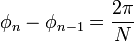 .
.
To show that

one merely assumes the converse, then multiplies both sides by 
The Fabry–Pérot interferometer uses interference between multiple reflections.
A diffraction grating can be considered to be a multiple-beam interferometer, since the peaks which it produces are generated by interference between the light transmitted by each of the elements in the grating. Feynman suggests that when there are only a few sources, say two, we call it "interference", as in Young's double slit experiment, but with a large number of sources, the process is labelled "diffraction".[1]
[edit]Optical interference
Because the frequency of light waves (~1014 Hz) is too high to be detected by currently available detectors, it is possible to observe only the intensity of an optical interference pattern. The intensity of the light at a given point is proportional to the square of the average amplitude of the wave. This can be expressed mathematically as follows. The displacement of the two waves at a point r is:
![U_1 (\mathbf r,t) = A_1(\mathbf r) e^{i [\phi_1 (\mathbf r) - \omega t]}](http://upload.wikimedia.org/wikipedia/en/math/0/d/2/0d23ddd0b5e0cda783c73f08cdfbb3ce.png)
![U_2 (\mathbf r,t) = A_2(\mathbf r) e^{i [\phi_2 (\mathbf r) - \omega t]}](http://upload.wikimedia.org/wikipedia/en/math/d/c/2/dc2f33fb3c5ddf3ff05c6d5ccde7243e.png)
where A represents the magnitude of the displacement, φ represents the phase and ω represents the angular frequency.
The displacement of the summed waves is
![U (\mathbf r,t) = A_1(\mathbf r) e^{i [\phi_1 (\mathbf r) - \omega t]}+A_2(\mathbf r) e^{i [\phi_2 (\mathbf r) - \omega t]}](http://upload.wikimedia.org/wikipedia/en/math/6/e/9/6e962b91e532ff965bc4f71f520ea724.png)
The intensity of the light at r is given by
![I(\mathbf r) = \int U (\mathbf r,t) U^* (\mathbf r,t) dt \propto A_1^2 (\mathbf r)+ A_2^2 (\mathbf r) + 2 A_1 (\mathbf r) A_2 (\mathbf r) \cos {[(\phi_1 (\mathbf r)-\phi_2 (\mathbf r)]}](http://upload.wikimedia.org/wikipedia/en/math/1/b/1/1b12ad6f313101121b8586bfe18bc0b9.png)
This can be expressed in terms of the intensities of the individual waves as
![I(\mathbf r) = I_1 (\mathbf r)+ I_2 (\mathbf r) + 2 \sqrt{ I_1 (\mathbf r) I_2 (\mathbf r)} \cos {[(\phi_1 (\mathbf r)-\phi_2 (\mathbf r)]}](http://upload.wikimedia.org/wikipedia/en/math/2/b/d/2bdddc0c9ebcb1eb10520a9c1a6e8966.png)
Thus, the interference pattern maps out the difference in phase between the two waves, with maxima occurring when the phase difference is a multiple of 2π. If the two beams are of equal intensity, the maxima are four times as bright as the individual beams, and the minima have zero intensity.
The two waves must have the same polarization to give rise to interference fringes since it is not possible for waves of different polarizations to cancel one another out or add together. Instead, when waves of different polarization are added together, they give rise to a wave of a different polarization state.
[edit]Light source requirements
The discussion above assumes that the waves which interfere with one another are monochromatic, i.e. have a single frequency—this requires that they are infinite in time. This is not, however, either practical or necessary. Two identical waves of finite duration whose frequency is fixed over that period will give rise to an interference pattern while they overlap. Two identical waves which consist of a narrow spectrum of frequency waves of finite duration, will give a series of fringe patterns of slightly differing spacings, and provided the spread of spacings is significantly less than the average fringe spacing, a fringe pattern will again be observed during the time when the two waves overlap.
Conventional light sources emit waves of differing frequencies and at different times from different points in the source. If the light is split into two waves and then re-combined, each individual light wave may generate an interference pattern with its other half, but the individual fringe patterns generated will have different phases and spacings, and normally no overall fringe pattern will be observable. However, single-element light sources, such as sodium- or mercury-vapor lamps have emission lines with quite narrow frequency spectra. When these are spatially and colour filtered, and then split into two waves, they can be superimposed to generate interference fringes.[2] All interferometry prior to the invention of the laser was done using such sources and had a wide range of successful applications.
A laser beam generally approximates much more closely to a monochromatic source, and it is much more straightforward to generate interference fringes using a laser. The ease with which interference fringes can be observed with a laser beam can sometimes cause problems in that stray reflections may give spurious interference fringes which can result in errors.
Normally, a single laser beam is used in interferometry, though interference has been observed using two independent lasers whose frequencies were sufficiently matched to satisfy the phase requirements.[3]

It is also possible to observe interference fringes using white light. A white light fringe pattern can be considered to be made up of a 'spectrum' of fringe patterns each of slightly different spacing. If all the fringe patterns are in phase in the centre, then the fringes will increase in size as the wavelength decreases and the summed intensity will show three to four fringes of varying colour. Young describes this very elegantly in his discussion of two slit interference. Some fine examples of white light fringes can be seen here. Since white light fringes are obtained only when the two waves have travelled equal distances from the light source, they can be very useful in interferometry, as they allow the zero path difference fringe to be identified.[4]
[edit]Optical arrangements
To generate interference fringes, light from the source has to be divided into two waves which have then to be re-combined. Traditionally, interferometers have been classified as either amplitude-division or wavefront-division systems.
In an amplitude-division system, a beam splitter is used to divide the light into two beams travelling in different directions, which are then superimposed to produce the interference pattern. The Michelson interferometer and the Mach-Zender interferometer are examples of amplitude-division systems.
In wavefront-division systems, the wave is divided in space—examples are Young's double slit interferometer and Lloyd's mirror.
Interference can also be seen in everyday life. For example, the colours seen in a soap bubble arise from interference of light reflecting off the front and back surfaces of the thin soap film. Depending on the thickness of the film, different colours interfere constructively and destructively.
[edit]Applications of optical interferometry
Main article: Optical interferometry
Interferometry has played an important role in the advancement of physics, and also has a wide range of applications in physical and engineering measurement.
Thomas Young's double slit interferometer in 1803 demonstrated interference fringes when two small holes were illuminated by light from another small hole which was illuminated by sunlight. Young was able to estimate the wavelength of different colours in the spectrum from the spacing of the fringes. The experiment played a major role in the general acceptance of the wave theory of light.[4] In quantum mechanics, this experiment is considered to demonstrate the inseparability of the wave and particle natures of light and other quantum particles (wave–particle duality). Richard Feynman was fond of saying that all of quantum mechanics can be gleaned from carefully thinking through the implications of this single experiment.[5]
The results of the Michelson–Morley experiment, are generally considered to be the first strong evidence against the theory of a luminiferous aether and in favor of special relativity.
Interferometry has been used in defining and calibrating length standards. When the metre was defined as the distance between two marks on a platinum-iridium bar, Michelson and Benoît used interferometry to measure the wavelength of the red cadmium line in the new standard, and also showed that it could be used as a length standard. Sixty years later, in 1960, the metre in the new SI system was defined to be equal to 1,650,763.73 wavelengths of the orange-red emission line in the electromagnetic spectrum of the krypton-86 atom in a vacuum. This definition was replaced in 1983 by defining the metre as the distance travelled by light in vacuum during a specific time interval. Interferometry is still fundamental in establishing the calibration chain in length measurement.
Interferometry is used in the calibration of slip gauges (called gauge blocks in the US) and in coordinate-measuring machines. It is also used in the testing of optical components.[6]
[edit]Radio interferometry
Main article: Astronomical interferometer

In 1946, a technique called astronomical interferometry was developed. Astronomical radio interferometers usually consist either of arrays of parabolic dishes or two-dimensional arrays of omni-directional antennas. All of the telescopes in the array are widely separated and are usually connected together using coaxial cable,waveguide, optical fiber, or other type of transmission line. Interferometry increases the total signal collected, but its primary purpose is to vastly increase the resolution through a process called Aperture synthesis. This technique works by superposing (interfering) the signal waves from the different telescopes on the principle that waves that coincide with the same phase will add to each other while two waves that have opposite phases will cancel each other out. This creates a combined telescope that is equivalent in resolution (though not in sensitivity) to a single antenna whose diameter is equal to the spacing of the antennas furthest apart in the array.
[edit]Acoustic interferometry
An acoustic interferometer is an instrument for measuring the physical characteristics of sound waves in a gas or liquid. It may be used to measure velocity,wavelength, absorption, or impedance. A vibrating crystal creates the ultrasonic waves that are radiated into the medium. The waves strike a reflector placed parallel to the crystal. The waves are then reflected back to the source and measured.
[edit]Quantum interference
| Quantum mechanics |
|---|
 |
| Introduction Glossary · History |
Background |
Fundamental concepts |
Formulations |
Equations |
Advanced topics |
Scientists Bell · Bohm · Bohr · Born · Bose de Broglie · Dirac · Ehrenfest Everett · Feynman · Heisenberg Jordan · Kramers · von Neumann Pauli · Planck · Schrödinger Sommerfeld · Wien · Wigner |

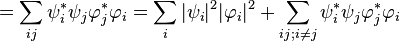
where the  s specify the different quantum "alternatives" available (technically, they form an eigenvector basis) and the ψi are the probability amplitude coefficients, which arecomplex numbers.
s specify the different quantum "alternatives" available (technically, they form an eigenvector basis) and the ψi are the probability amplitude coefficients, which arecomplex numbers.The probability of observing the system making a transition or quantum leap from state Ψ to a new state Φ is the square of the modulus of the scalar or inner product of the two states:

where  (as defined above) and similarly
  are the coefficients of the final state of the system. * is the complex conjugate so that
  , etc.
(as defined above) and similarly are the coefficients of the final state of the system. * is the complex conjugate so that , etc.Now let's consider the situation classically and imagine that the system transited from  to
to  via an intermediate state . Then we would classically expect the probability of the two-step transition to be the sum of all the possible intermediate steps. So we would have
to via an intermediate state . Then we would classically expect the probability of the two-step transition to be the sum of all the possible intermediate steps. So we would have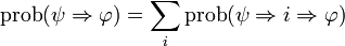
 ,
,
The classical and quantum derivations for the transition probability differ by the presence, in the quantum case, of the extra terms 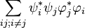 ; these extra quantum terms represent interference between the different
  intermediate "alternatives". These are consequently known as the quantum interference terms, or cross terms. This is a purely quantum effect and is a consequence of the non-additivity of the probabilities of quantum alternatives.
; these extra quantum terms represent interference between the different intermediate "alternatives". These are consequently known as the quantum interference terms, or cross terms. This is a purely quantum effect and is a consequence of the non-additivity of the probabilities of quantum alternatives.The interference terms vanish, via the mechanism of quantum decoherence, if the intermediate state is measured or coupled with the environment.[7][8]
is measured or coupled with the environment.[7][8][edit]See also
- Active noise control
- Beat (acoustics)
- Coherence (physics)
- Diffraction
- Double-slit experiment
- Young's Double Slit Interferometer
- Haidinger fringes
- Hong–Ou–Mandel effect
- Interference lithography
- Interferometer
- List of types of interferometers
- Lloyd's Mirror
- Moiré pattern
- Newton's rings
- Thin-film interference
- Optical feedback
- Retroreflector
- Upfade
- Multipath interference
- Inter-flow interference
- Intra-flow interference
- Bio-Layer Interferometry
- N-slit interferometric equation
[edit]References
- ^ Richard Feynman, 1969, Lectures in Physics, Book 1, Addison Wesley, Reading, Mass.
- ^ WH Steel, Interferometry, 1986, Cambridge University Press, Cambridge
- ^ R. L. Pfleegor and L. Mandel, 1967, "Interference of independent photon beams", Phys. Rev., Volume 159, Issue 5. pp. 1084–1088.
- ^ a b Max Born and Emil Wolf, 1999, Principles of Optics, Cambridge University Press, Cambridge.
- ^ Greene, Brian (1999). The Elegant Universe: Superstrings, Hidden Dimensions, and the Quest for the Ultimate Theory. New York: W.W. Norton. pp. 97–109. ISBN 0393046885.
- ^ RS Longhurst, Geometrical and Physical Optics, 1968, Longmans, London.
- ^ Wojciech H. Zurek, "Decoherence and the transition from quantum to classical", Physics Today, 44, pp 36–44 (1991)
- ^ Wojciech H. Zurek, "Decoherence, einselection, and the quantum origins of the classical", Reviews of Modern Physics 2003, 75, 715.
[edit]External links
| Wikimedia Commons has media related to: Interference |
| Look up interference in Wiktionary, the free dictionary. |
- Expressions of position and fringe spacing
- Java demonstration of interference
- Java simulation of interference of water waves 1
- Java simulation of interference of water waves 2
- Flash animations demonstrating interference
- Lissajous Curves: Interactive simulation of graphical representations of musical intervals, beats, interference, vibrating strings
- Animations demonstrating optical interference by QED

The Mach–Zehnder interferometer is a device used to determine the relative phase shift between two collimated beams from a coherent light source. The interferometer has been used, amongst other things, to measure small phase shifts in one of the two beams caused by a small sample or the change in length of one of the paths. The apparatus is named after the physicists Ludwig Mach (the son of Ernst Mach) and Ludwig Zehnder.
The Michelson interferometer is a Mach–Zehnder interferometer that has been folded back upon itself. The principal difference is that in the Michelson interferometer, the beam splitting optic is also used to recombine the beams.
Contents |
[edit]How it works
[edit]Set-up
A collimated beam is split by a half-silvered mirror. The two resulting beams (the "sample beam" and the "reference beam") are each reflected by a mirror. The two beams then pass a second half-silvered mirror and enter two detectors ("detector 1" and "detector 2"). It is important that the fully silvered and half-silvered surfaces of all mirrors, except the last, face the inbound beam, and that the half-silvered surface of the last mirror faces the outbound beam exiting in the same orientation as the original collimated beam. That is, if the original beam is horizontal, the half-silvered surface of the last mirror should face the horizontally outbound beam.
[edit]Properties
It is important to consider that the medium of a mirror is what lies behind it; that is, if a glass substrate has its half-silvered or fully silvered surface facing the inbound beam, then the inbound beam travels through air and is reflected off the surface of a glass medium. If, however, the half-silvered or fully silvered surface faces away from the inbound beam, then the inbound beam travels through glass and is reflecting off the surface of an air medium.
The following rules apply to phase shifts due to material:
- Reflection or refraction at the surface of a medium with a lower refractive index causes no phase shift.
- Reflection at the surface of a medium with a higher refractive index causes a phase shift of half of a wavelength.
- The speed of light is slower in media with an index of refraction greater than that of a vacuum, which is 1. Specifically, its speed is:
 , where c is the speed of light in vacuum and n is the index of refraction. This causes a phase shift increase proportional to (n − 1) × length traveled.
Given the above rules, mirrors, including half-silvered mirrors, have the following properties:
- A ½ wavelength phase shift occurs upon reflection from the front of a mirror, since the medium behind the mirror (glass) has a higher refractive index than the medium the light is traveling in (air).
- If k is the constant phase shift incurred by passing through a glass plate on which a mirror resides, a total of 2k phase shift occurs when reflecting off the rear of a mirror. This is because light traveling toward the rear of a mirror will enter the glass plate, incurring k phase shift, and then reflect off the mirror with no additional phase shift since only air is now behind the mirror, and travel again back through the glass plate incurring an additional k phase shift.
[edit]Observing the effect of a sample
Without a sample, there is no phase difference in the two beams in detector 1, yielding constructive interference. Both beams will have undergone a phase shift of (wavelength + k) due to two front-side reflections and one transmission through a glass plate. At detector 2, there is a phase difference of half a wavelength, yielding complete destructive interference. The reference beam into detector 2 has undergone a phase shift of 0.5 ×(wavelength) + 2k due to one front-side reflection and two transmissions. The sample beam into detector 2 has undergone a (wavelength + 2k) phase shift due to two front-side reflections and one rear-side reflection. Therefore, when there is no sample, only detector 1 receives light.
If a sample is placed in the path of the sample beam, the intensities of the beams entering the two detectors will change, allowing the calculation of the phase shift caused by the sample.

[edit]See also
- Interferometer
- Elitzur–Vaidman bomb-tester
- Time-bin encoding
- Jamin interferometer
- Classical interference microscopy
- Dual polarisation interferometry
[edit]Flow visualisation techniques
[edit]References
- Ludwig Zehnder, Z. Instrumentenkunde 11 (1891) 275.
- Ludwig Mach, Z. Instrumentenkunde 12 (1892) 89.
- Mach, Ernst (2003). The Principles of Physical Optics. Dover. ISBN 0-486-49559-0. p. 170. (First published in German in 1926.)